Library Contents Search the Library RV Tech Library Help Page Site Map About Us Tiffin RV Network TRVN Classifieds Campground Reviews Photo Gallery TRVN Store
Appliances Batteries Boondocking/Dry Camping Chassis Clubs & Forums Electrical Electronics Engines Exterior Maintenance Generators Heating & Air Conditioning Interior Maintenance Misc Items Operating Tips Plumbing Red Bay Safety & Health Storage Supplier Contacts Tires and Wheel Rims Towing Transmissions Weighing
Dirt Devil CV950 Central Vacuum System
|
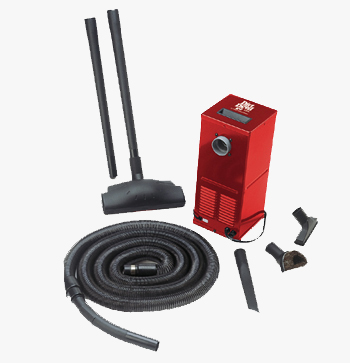
Overview: Central vacuum systems can be a valuable space saver in an RV. The Dirt Devil CV950 is a popular central vacuum for RVs and is the original equipment choice of Tiffin Motorhomes. The CV950 is a very compact unit with a great deal of suction and airflow. In addition to the normal accessory kit many RVers also add some form of turbo brush. These brushes utilize the vacuum cleaner's airflow to drive an impeller to spin a brush. This brush makes it much easier to remove pet fur from carpeting and furniture. An important consideration is the actual placement of both the power unit and the inlet valve assembly. The power unit itself is generally mounted in the basement. The power unit will require emptying of the bag when full and this keeps the mess out of the main coach area. It also keeps the exhausted air and noise in the basement area rather than in the coach interior. Because the power unit does exhaust air you will need to locate it in a large basement storage area or a vented compartment. If it is located in a small sealed compartment it will pressurize the compartment and you won't have any airflow at the vacuum head.
|
|
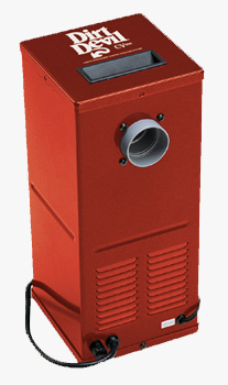
The inlet valve consists of a wall mounted hose connection covered by a spring loaded flap valve. When the flap is raised a switch within the valve assembly will turn on the power unit. When the hose is removed and the flap returns to the closed position the power unit will stop. The inlet valve is connected to the central unit via a short hose. The interior cleaning hose is wire reinforced and while only 7' long when collapsed, it will stretch to close to 30'. You will want to locate the valve assembly somewhere mid coach to eliminate the operator fatigue from stretching the hose to it's limit.
Installation Instructions:
1. Locate unit centrally so that the area to be cleaned can be conveniently reached with a standard 30' hose. Also, locate a grounded electrical receptacle for easy plug-in connection of motor cord. Route the power cord so that it does not rest on any sharp edges or pinch points.
2. All dimensions below are approximate. To determine the best configuration for your installation temporarily install the unit for best valve location. Be sure to allow enough room to remove the filter bag cover. The unit can be mounted either horizontally or vertically.
3. Determine the valve location and cut a 2-1/4" wide by 3-3/4" high opening. If the unit is mounted directly next to the valve assembly you will need to make sure that the valve is a minimum of 9-7/8" above the floor if the unit is installed vertically or 1-3/4" above the floor if installed horizontally. This is to ensure that you have enough clearance for the hose. If the central unit is not located immediately next to the valve assembly, such as in the basement, this is not necessary.
4. Do not vent into a wall, ceiling, or concealed space. Unit must be vented with an interior vent in the location that the canister is placed.
5. Place the CV950 canister in it's approximate location before installing the inlet valve, mounting plate, and inlet reducer. Be sure that the connection hose can reach between the two points.
6. The inlet valve switch should be wired at this point. Insert the pre-stripped ends of the wires into the holes on the back of the inlet valve. Press the wires in firmly and they will lock in place. Pull lightly to test that they're locked in. Connect the other ends of the wires to the wire leads from the relay (located on the bottom of the power unit) with the wire nuts provided.
7. Install the inlet reducer to inlet connector. If it is a loose fit, feel free to add some glue to hold it in place. Assemble the inlet valve to the wall with the mounting plate, using the 4 screws provided. Be sure that the tabs on the mounting plate face away from the inlet valve.
8. Secure the unit to the floor or wall with the brackets that are provided. Place square heads of the mounting bolt into the channel of the canister. Tighten the nut to hold brackets in desired location. Anchor the leg of the bracket to the floor or wall with the brackets provided.
9. Plug in the power cord from the unit to the electrical outlet. The CV950 draws 11.3 amps so a 15 amp circuit is adequate to run it.
Lift the lid to test it's operation. You are now Finished!
Submitted by Mark Quasius - 1/30/06
Click Your browser's "Back" button to return to the previous page
or chose another category from the side menu.
The RV Tech Library is brought to you by the TiffinRVnetwork
Absolutely No Affiliation exists between this group and Tiffin Motor Homes Inc or the Allegro Club. This website neither endorses or discourages the use or purchase of a Tiffin product. All references, suggestions, comments, etc. contained herein are the opinions/experiences of the posters and not those of Tiffin Motor Homes Inc. or the website administrators.
|
|